While building a new Dust Collection system for the updated home shop, I realized that my old 110V remote switch would not be usable. After investigating several commercial solutions, I found that they either had large or uncomfortable remotes, didn’t have optional add-on remotes, or were just far more expensive than I could justify for the task. They also were either radio remote or remote switched, not a combination of actions.
I read how someone had found this $25 remote control on Amazon to control their dust collector, but the thought of driving 240V at 23A startup through that tiny relay didn’t seem like a safe or a reliable, long-term solution. It did provide some inspiration, however, and the result is documented here.
Requirements
- Allow starting the Dust Collector via a radio remote control.
- Allow starting the Dust Collector via a remote switch on the blast gate.
- Support 110 or 220 VAC blowers up to 5 HP in size (via Contactor).
- Be easy to build with commonly available parts, requiring minimal skill to assemble.
- Permit substitution of parts – no specific part is critical.
Parts
I was able to source all parts from Amazon, and had them in my hands within 24-hours. I could have saved a few dollars by using alternate parts that took a week to be delivered, but opted to have everything for a weekend build.
Parts List
None of the parts listed here are critical and can be substituted with any equivalent component.
|
Part
|
Price
|
Source
|
|
Project Box / Electrical Enclosure
|
$20.00
|
Amazon
|
|
Transformer, 8/16/24 VAC for thermostat or doorbell*
|
$15.00
|
Amazon
|
|
AC-12VDC converter/regulator
|
$12.00
|
Amazon
|
|
Remote Switch, Single Button**
|
$8.70
|
Amazon
|
|
Contactor, 2-pole, 250VAC/40A inductive rating
|
$12.00
|
Amazon
|
|
Terminal Block, 8 position (6 poles needed)
|
$8.00
|
Home Depot
|
|
Receptacle, R6-20, 250V / 20A
|
$5.50
|
Home Depot
|
*Only 24VAC is required for this project. This model was selected for faster delivery time.
**I opted for an alternate remote switch that provided one transmitter with 2 buttons and 2 receivers so I could control an air-filter as well from a single transmitter. The 2-channel device cost an additional $4.00.
I did not provide links for the terminal block and receptacle as they are easily obtained from any local hardware store. Miscellaneous parts such as terminal lugs and cable clamps are not listed and are easily obtained from local sources.
“Poor Man’s Alternative”
Before we get into the construction details, there’s a simple alternative to this if you already have a 120V remote switch but now have a 240V dust collector. It simply requires a 2-pole contactor with a 120V coil, a small project box, and a set of 120V and 240V extension cords. The 240V cord should be made from #12 wire for a 20A circuit.
- Mount the contactor in the project box.
- Cut both of the extension cords; discard the 120V socket end.
- Cut the 120V cord close to the socket end.
- Cut the 240V cord so that the plug can reach the 240V outlet and the socket can reach the dust collector cord. These cords should be just long enough to reach the 240V outlet and the dust collector cord – 12-18” max!
- Wire the plug end of the 120V extension cord directly to the contactor coil.
- Wire the plug end of the 240V extension cord to the L1/L2 side of the contactor.
- Wire the socket end of the 240V extension cord to the T1/T2 side of the contactor.
- Connect the neutral / ground wire ends of the 240V extension cord together with a wire nut.
Plug the 120V cord into your existing 120V remote switch, then plug the 240V cord into the 240V outlet. Plug the dust collector into the 240V socket end of the extension cord. Your 120V remote switch will drive the contactor coil and complete the 240V circuit.
Construction
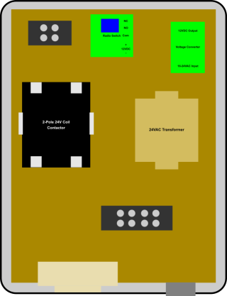 Construction started by cutting a piece of Masonite to fit inside the project box. The box I used required a panel 5-7/8 by 7-7/8”. I then started laying out the position of the various components, making sure I had room to route wires and kept the high and low voltage connections separated. Once I was happy with the positions, I drilled mounting holes and secured the components to the panel, making sure that nothing exceeded the height of the enclosure.
The radio switch came with a small plastic enclosure, so I drilled and countersunk holes in the enclosure. I drilled matching holes in the Masonite and used a pair of 6-32 flat-head machine screws to secure it. I covered the screw heads with electrical tape. The electronic module was a somewhat loose fit in the enclosure, so I put a small bit of self-adhesive weatherstrip on top of the relay, which helped to secure the module. A dab of silicone caulk on the back would accomplish the same thing, although this probably wasn’t necessary.
I drilled a 1.375” hole in the bottom of the enclosure to mount the receptacle. Holding a cover plate against the outside of the enclosure, I marked the location for the two mounting holes. The two holes that usually attach the cover plate will secure the receptacle to the enclosure.
Low Voltage Wiring
There are two sets of low-voltage wiring – 24V AC and 12V DC. The transformer provides the 24V AC power to the contactor and the Voltage Converter. The Voltage Converter is a simple rectifier / regulator circuit that converts the AC input to DC and delivers filtered 12V DC at a max of 1A. This drives the radio receiver, which has a current draw of just a few milli-amps. Note – since the transformer had a 16VAC option, I used that to drive the Voltage Converter so it would run a bit cooler. The illustrations assume a single-output 24VAC transformer. If you decide to follow this method, the connection to the Voltage Converter will connect to the center terminal, while the NO terminal connects to the outer terminal.
Low Voltage DC Wiring
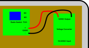 Start by connecting the output of the Voltage Converter to the Radio Switch, using red and black wires. Be mindful to connect plus to plus and minus to minus! The polarity on the parts you select and receive may not match this illustration, so check your actual parts carefully. I used #18 wire for this connection, which I pulled from some thermostat control wire I had handy.
Low Voltage AC Wiring
Using the same #18 thermostat wire, I chose the yellow and blue wires for low-voltage AC connections. The colors don’t matter for low volt AC, but I selected Blue for the common / non-switched side of the circuit and yellow for the control side.
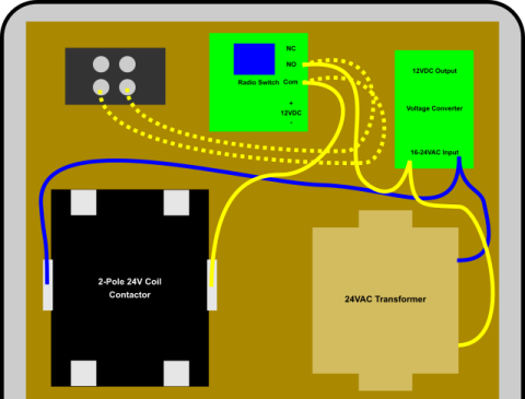 Start by connecting one piece of blue wire from the transformer to one side of the Voltage Converter, then continue to the coil on the contactor. I used a spade connector on the transformer side and a push-on connector on the contactor. I did not cut this wire, but simply stripped extra length from one end, carefully cut the insulation and slid it toward the end. I folded the wire and inserted it into the terminal of the Voltage Converter.
I did the same with a yellow wire, with a spade lug on the transformer end. The other end was simply twisted and secured to the Normally open (NO) connection on the Radio Switch. A second yellow wire used a push-on connector to connect to the other side of the Contactor coil.
Since I wanted to be able to place an activation switch directly onto the Blast Gates in the future, I added two yellow wires between the NO and COM connections to a 2-pole terminal block. Shorting this connection is the same as activating the Radio Switch and will turn on the Contactor. This wire and terminal block are optional. Again, the actual positions of the connections on your devices may vary, so consult the documents and markings on your devices.
High Voltage Wiring
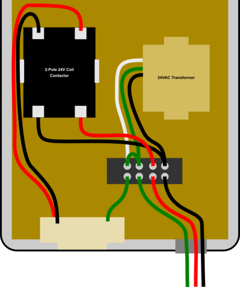 WARNING – The 120/240 voltages can cause injury or death. Use caution when wiring these components, and seek assistance if you are unsure or unfamiliar with this task!
 Depending on the dust collector you are using, you will need to use #12 (20A) or #10 (30A) wiring for this task. Also – the color of your wires may vary. If you use a 240V Extension Cord on the input side, it will likely use Black, White, and Green wires. If you are wiring this directly to the 240V service, you may have Black, Red, White, and bare copper wires.
3-Wire 220V Source
Black – hot L1
White – hot L2
Green – Neutral / Ground
4-Wire 220V Source
Black – hot L1
Red – hot L2
White – Neutral
Green – Ground
Terminal Strip
The terminal strip (barrier strip) provides connection points for the high-voltage input.
|
Position:
|
1
|
2
|
3
|
4
|
|
Use:
|
Neutral
|
Ground
|
L2 Input
|
L1 Input
|
| |
|
|
|
|
Position 1 and 2 are bonded together with a jumper.
All wires that connect to the Terminal Strip use spade lugs. The wires that connect to the contactor use the screw compression connector. I removed the push-on adapters from the contactor to minimize exposure to high voltage inside the enclosure. I used a scrap of plexiglass secured to the top of the contactor with double-sided foam tape to cover the high-voltage area once all the connections were made.
Adapting to 110V Control
.png) The same design and components can be used to switch a 110V dust collector. The only parts change will be to use the appropriate receptacle. The only wiring change would be to eliminate the L2 switch path through the contactor and move the neutral wire of the transformer to the neutral input.
The same design and components can be used to switch a 110V dust collector. The only parts change will be to use the appropriate receptacle. The only wiring change would be to eliminate the L2 switch path through the contactor and move the neutral wire of the transformer to the neutral input.
For 110V wiring, you should not open the neutral. Only one pole of the contactor will be used. DO NOT connect the white wire to the contactor! This violates most electrical codes and will present a safety hazard that could cause injury or death.
To wire this for 110V:
- The Red input wire shown in the diagram will be white.
- Eliminate the red wire that connects from Terminal Strip position 3 to the contactor.
- Replace the Red L2 wire from the receptacle to the contactor with a White wire that connects the receptacle to the Terminal Strip position
- Move the White wire of the 24VAC Transformer from Terminal Strip Position 1 to Position 3.
Assembly Notes & Testing
Once everything was physically assembled to the backer board, I wired the connections, trimming everything to length. I left the input and output of the Voltage Converter disconnected, which prevented it from receiving power or providing power to the radio receiver.
I started by mounting the unit on the wall and connecting the 220VAC source. This ran from a Gem box in the wall, through a 2” piece of ¾” conduit into the box. Leaving the box open so I could watch for anything “unusual”, I turned on the circuit breaker. Seeing no smoke or flames, I carefully measured the voltage on the input terminal strip – verifying 110V between each leg and neutral, and 220V between the 2 legs using the 600V range on my multimeter. Switching to the 200V range, I measured the output of the transformer, verifying 8, 16, and 24VAC were present on the terminals.
I turned off the breaker and connected the output of the transformer to the input of the Voltage Converter. Again, watching for anything unusual, I turned on the circuit breaker. Switching the multimeter to 20V range DC, I confirmed that the output of the Voltage Converter was 12V.
At this time, the power switch on the dust collector motor was off, so I tested the contactor by shorting the contacts on the upper terminal block (shown by dotted yellow lines). The contactor made a solid “CLICK” when I shorted the connection, and another audible click when I removed the short. Any N/O switch can be connected in parallel across these terminals. I will add wire to small micro-switches on the blast gates, so simply opening a gate will turn on the DC.
I turned off the circuit breaker, then connected the output of the Voltage Converter to the Radio Receiver. After turning on the circuit breaker, I pressed the transmitter button and heard the contactor CLICK. Releasing the transmitter button removed power to the contactor, so the receiver needed to be programmed. I used a small stick to press the program button three times, as per the instructions. I then pressed the “A” button on the transmitter. After a few seconds, the program LED turned off. Pressing the “A” button once closed the contactor, and pressing it a second time opened the contactor. I could now test the blower!
I plugged the Dust Collector motor into my remote switch and turned the switch on the motor to the “on” position. After pressing the “A” button on the transmitter, the blower roared to life!
The last step was to turn the circuit breaker off, place a small piece of double-sided foam tape onto the transformer, and then stick the Plexiglas panel onto the tape to prevent exposure to the high-voltage terminals. I closed and latched the box and turned the circuit breaker on.
The Final Result

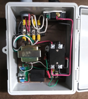 The picture shown here is the final result (without the Plexiglas shield) showing the wiring. Due to space constraints and the location of the 220V wiring box, this is rotated 180 degrees from the diagrams in this document. Actual orientation is not important.
The small green jumper wire in the lower-right was used to test the remote switch activation and is not part of the final project.
To wire remote-start switches to the blast gates, all that is needed is to run a 2-conductor low-voltage wire from this control box to the blast gates you want to control. A micro-switch should be mounted on the blast gate such as the switch lever is actuated when the gate is closed. Attach the low-volt wire to the Common and N/C pins. This connection will be open when the gate is closed. Opening the gate releases the switch actuator arm and returns the switch contacts to the Normally Closed connection. This passes the low-voltage to the contactor and starts the blower. Note that the switches are wired in parallel, and that will allow any gate to be opened and start the blower. All gates must be closed to stop the blower.