Rockets!
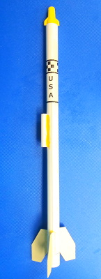 Who doesn't like rockets? This build is simple, requires a sheet of paper, some business cards or old greeting cards, a bit of Balsa wood, and a soda straw. This is a great way for Scouts to earn a Rocketry badge or introduce Newtons laws to a science class. If you're here for the launcher and controller - click here! The rocket shown here is built using these plans, and uses an electrical wire nut for a nose cone. This is a "feather-weight" rocket and being little more than a sheet of paper has no parachute or streamer and generally won't be re-used. If a streamer is desired, include 30" of carpet thread glued when the paper is half-way rolled up. Secure the loose end to the nose cone and tie 8-12" of bright nylon cloth about 3" from the nose cone. The streamer must be tightly rolled to fit in this narrow rocket.
Paper Rocket Plan (Rocketry Merit Badge)
There are just a few simple things needed to prepare paper rockets!
- A 1/2" wood or plastic dowel 12-14" long. The diameter must be exactly 1/2"!! You will also need some short pieces to shape into nose cones. Balsa wood is light and easy to shape. Any other lightweight material can be used for nosecones - the photo shows an electric wire nut!
- A sheet of typing paper, or the printout of the image below. The image below can be printed full-size on an 8.5x11 sheet of paper. If you trim 1/4" from the right side, the images should wrap around perfectly and provide guidelines for fins and the launch lug. The instructions will disappear inside the rolled paper.
- 3 business cards or an old greeting card for the fins.
- A soda straw - paper works best. This will be the launch guide lug. If you use a plastic straw, PVA glue (Gorilla Glue) or super-glue (CA) should be used (by an adult) to attach the guide lug.
- Glue - either white craft glue or yellow wood glue. A glue stick can be helpful to keep the paper from unrolling while the stronger glue dries.
- Rubber bands or binder clips - used to secure the paper around the dowel while the glue dries.
A hot-melt glue gun can be helpful to tack the fins in place while the glue dries. DO NOT attach fins with hot-glue! The rocket motor gets hot and the fins will fly off when the hot-melt glue melts! Finless rockets have a mind of their own!!
- Roll the paper along the long edge around the dowel. Roll it tight and let go to "train" the paper to the shape. Roll one turn, then smear a bit of glue on the paper at least near each end and the middle - don't get any glue on the dowel! Continue to roll tightly, then smear glue on the edge and complete the roll. Place at least 3 rubber bands around the paper to keep it in shape, then slide it off the dowel. Set it aside to dry - at least 1 hour. You can prepare several tubes if you wish and create a fleet!
- Cut the cardstock to 2" wide by 1.5" high using the business cards or greeting cards to prepare the fins. You should score three lines in each piece. You can do this with the back of a table knife or a fine-point pen and a ruler. You don't want to cut - just create a straight line where the paper will be folded.
- The top of the part should be scored exactly in the center of the paper.
- Turn the paper over and score a line 1/8" from each end.
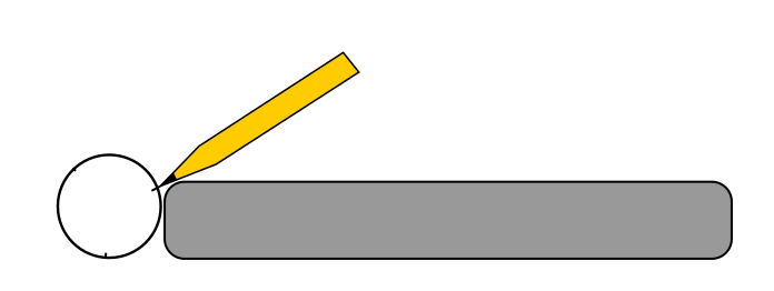
- Fold the fin paper on the score lines. Make the short edge folds first, then fold the center. Place a dab of glue inside the fold and use a binder clip or clothespin to secure the two halves of the fin together - set aside to dry. When the fin is folded correctly, it will look like a "T" when you look at it from the edge.
You can prepare several fin sets. It might be fun to try different fin designs!
- After the fins have dried, you can cut them to "fin shape". Several example shapes are illustrated. The two right-most designs will allow the rocket to stand on its fins for display without the fins getting too close to the exhaust.
- Time to attach the fins! If you are using the printed sheet below, there are 3 vertical guide lines and a baseline to help with aligning the fins.
- If you are using a plain sheet of paper, you will need to make your own guides - it's easy! Start by creating a baseline. Roll one of the rubber bands to 1/2" from the bottom of the rocket body, and trace a thin pencil line around using the rubber band as a guide, then remove the rubber band.
- Mark the fin positions. Make a random mark at the bottom of
 the rocket tube. Now place two more marks on the rocket body approximately 1/3 of the way around from the first mark in each direction. "Close enough" will work. Grab your phone and lay it on the table, then place the rocket body against your phone. Line up one of the 3 marks, then use your phone as a guide to extend that line about 1.5" up the body. Repeat for each of the other two marks.
- Place a small mark halfway between two of the fin guides. Using the same method, create an alignment guide line about halfway up the rocket body.
Place some glue on the base (root) of each fin, then using the guide marks and baseline, place the fin onto the body. This is when some hot glue works great. After adding the glue and attaching the fin, place a drop of hot glue at each end (top and bottom edge) of the fin and hold it until it cools. This will hold the fin in position while the liquid glue dries. Place the rocket body into a glass or cup with the fins up so they don't bend and can dry straight.
- Cut a piece of soda straw about 1.5" long and glue it to the alignment mark that's about halfway up the body and between two fins. If you are using a plastic straw, it is recommended that you either place some tape around both ends of the straw and the rocket body to secure it - very few glues will bond paper and plastic very well. Adding a "fillet" of glue between the straw and the body will help strengthen this joint - simply place a thin stream of glue between the straw and the body and let it dry. Repeat on the other side.
- Create a "nose cone". A piece of 1/2" dowel about 1" long is adequate. It can be sanded to a round or slightly pointy configuration. It should fit into the top of the rocket body. A wrap or two of a thin strip of masking tape about halfway up the cone will prevent it from sliding into the body.
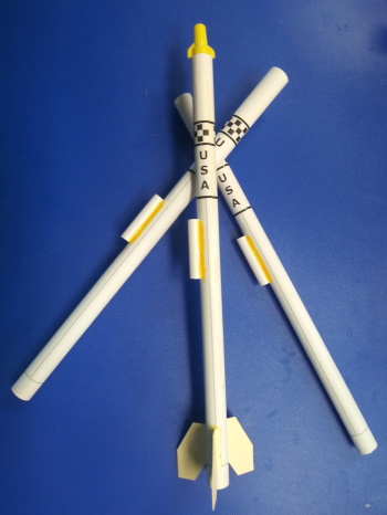
The following image can be downloaded as a PDF and printed at full-size. Trim the right margin off so the rings and checker-board line up.

Update - June 2024 - 3D Printed Rocket
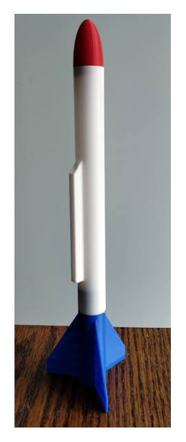 This was such a big hit with the grandkids that the extended family planned their July 4 celebration to include a launch in our back yard. With so many young kids, making the paper versions in the morning would be a challenge, so I designed a small rocket that could be 3D Printed in 3 colors, printing six at a time. These are about 22g and still considered "featherweight". Like the above, they are designed to use a Half-A type motor. The parts are snap-fit, with the body to fin being a bit tighter than the nose to body, so young children might need an adult's help to mate the body and fin can.
These are designed to be semi-reusable - with a half-A engine, you should be able to get 2-3 flights before the heat deforms the body tube enough to prevent safe flights. I did try an A-10 engine but the heat from the ejection charge softened the body tube enough to severely deform it, preventing a second flight. The body tube uses a "Walls:1" setting to keep it as light as possible, so there isn't much heat resistance. The design could be changed in two ways to make it more reusable:
- Increase the size about 25-33%, allowing the body walls to be made thicker, then use a wall setting of 4 or more.
- Use a cardboard insulator tube in the fin-can to better isolate the motor heat from the plastic.
Note that you will need to make some adjustments to the design to make the body and other parts fit if you make the walls thicker.
The body incorporates an integrated launch lug sized for a standard 1/8" steel rod. The fin can has a small ring at the top to prevent the motor from running through, although the slight taper of the engines generally prevents this.
Both the Fin Can and Nose Cone have rings (requires supports for the nose cone) to attach a recovery cord. Use at least 36" of Kevlar carpet thread to connect these before assembly, being sure to pass the thread through the body tube before connecting both ends. A small nylon streamer can be attached near the nose cone.
You can Download a ZIP file containing the 3 STL files. These should work on any FDM type printer without modification. The body tube uses a brim, and the nose cone requires supports unless you remove the recovery lug.
Prep for Launch
 Insert a 1/2-A or A series engine into the bottom of the rocket body. Wrap the end of the engine with tape to obtain a secure fit, and add 2 additional thin wraps of tape to the bottom of the engine to prevent it from entering the body - the engine must remain extended at least 1/4" from the bottom of the rocket. The 1/2-A rocket motors are small enough to be safe for a backyard flight. A full "A" motor needs about 100 feet of clear area in all directions for a safe flight. Most school yards or fields will be OK for these.
Place a "puff" of powdered chalk into the body tube. No more than 1" of the body should be loaded with chalk to maintain flight stability! This will create a small brightly-colored cloud when the recovery charge fires. Don't use any chalk if you have installed a recovery streamer!
Place the nose cone on the top of the rocket body. If the fit is loose, add a wrap of tape to the nose cone about 1/4" above the bottom - the bottom should fit into the body but should not be able to disappear into the body.
Present the rocket to the Range Safety Officer (RSO) for inspection. The RSO will install the igniter and ready the rocket for flight by placing the rocket onto the launch rod and connecting the launch controller to the igniter. A Flight Safety Officer (FSO) will then - possibly with the rocket owner - verify the connection, launch the rocket, and monitor the flight. The RSO and FSO can be the same person in small groups.
The Launch Pad & Controller
One launch pad is needed and is generally built by an adult. It requires about an hour to assemble. Start by obtaining the parts:
- A block of scrap wood, at least 15" long and 4-6" wide and 3/4" thick. Alternatively - a 12" square and 3" square of plywood.
- A brick or a large Ziplock bag of sand
- A steel rod - 1/8" or 3/16" diameter by 36" long. Home Depot type stores or hobby shops sell these.
- A 12" jumper cable with alligator clips.
- Two pushbutton switches (or "momentary" toggle switches). Hobby Shop or automotive parts store.
- A 12V indicator bulb or LED. (auto-parts store)
- A 2-gang electrical box, blank cover, and a cable clamp. Home Depot type store.
- 25-foot roll of "zip wire" (lamp wire). Home Depot type store.
- Electrical tape.
- Soldering Iron and solder, or miniature wire nuts
- 6V Lantern battery
- Tin Can lid - 3" or larger
Optional Items
- Wire Lugs (2) for lantern battery or Alligator Clips for spring-terminal type battery.
- Powdered "snap-line" chalk - bright color like Red or Orange
- Landscape spike (2) - metal or plastic
Building the Launcher (Woodworking merit badge)
- Start by cutting 3" from one end of the board. Glue (or screw) the small piece to the center of the large
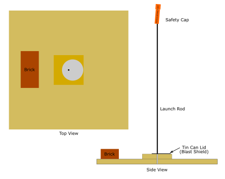 piece to double the thickness. If you are using a plywood square, simply glue or screw the small square in the middle of the larger square.
- Drill a hole the same size as your steel rod dead-center of the small board. Drill all the way through both boards. Test fit the rod to make sure it fits snugly into the hole.
- There are two methods to stabilize the launcher - either placing a brick or bags of sand on the board, or drilling holes at each end of the board and driving the landscape spikes through the board into the ground. Decide on your method of stabilization and drill the holes in the board if you will use the landscape spike method.
- Drill a hole the same size as your steel rod in the tin can lid, about 1/2 to 3/4" off-center. This is the "blast plate" that will prevent the wooden base from becoming charred.
Safety First! It's very easy for someone to bend over the launch rod and be poked by the rod when it is on the ground. A short piece of pipe with one end closed and brightly painted can be placed over the rod to prevent accidents. Placing the launcher on a table minimizes this risk but will probably require an adult to place the rocket on the launcher.
That's all that's needed - on to the launch controller!
Building the Controller (Electronics merit badge)
 The controller mounts two switches and an indicator lamp on a blank cover plate. Two wires connect to this electrical box - one short one from the battery and the other long one to the launch pad. The launch pad wire should be at least 20 feet long. This is an idea of what the controller will look like. There are two buttons - TEST and FIRE. When you press the TEST button, current will flow from the battery, through the light, through the igniter, and the light will illuminate if the circuit is good. The igniter will not fire because the lamp has lower resistance than the igniter and thus illuminates. The FIRE button short-circuits the lamp, allowing all of the current to flow to the igniter, launching the rocket. To launch the rocket, you need to press the test button and verify the light illuminates. If the sky and launch area are clear, continue to hold the TEST button and press the FIRE button. It may take a second for the motor to ignite and the rocket to lift-off. Release both buttons after the rocket has lifted off. The RSO should replace the safety cap on the launch rod and FSO should monitor the flight along with the rocket owner.
Controller Schematic
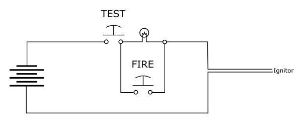 This is the schematic, or wiring plan, for the controller. If you are using automotive switches, they may have screw terminals, which will eliminate the need for most, if not all, soldering. If you are using screw terminals, you should use Spade Connectors on the ends of the wire. These can easily be crimped with a tool to provide a secure connection. It is very difficult to wrap and secure the stranded wire around screw terminals, and the spade lugs will prevent any stray wires from short-circuiting and possibly causing a misfire event.
Construction
- Drill 3 holes in the electrical cover plate to match the requirements of the light and two switches. Make sure that these holes are far enough from the edges to allow the switch to fit inside the electrical box! Mount the lamp and switches into the holes. If you are using an LED lamp, it is polarity sensitive. Connect it to the battery to determine which lead connects to the (+) terminal of the battery before proceeding.
- Pull a 7-foot length of Zip wire off of the spool - this will connect to the battery. Measure 5-feet from the end and split the wire for about 6-inches, as shown below. Locate the "ribbed" wire and cut it in the middle of the separated part. Fold the wire in half where shown and wrap both wires together with 20 turns of electrical tape about 9-inches from the fold. This tape will protect the wire when it is clamped later

- Pop out one of the plugs on the side of the electrical box and insert a clamp. Feed the folded wire through the clamp until about a foot of wire is inside the box. The wire will be pulled back after the switch and lamp connections are made.
- Attach Alligator Clips to the end of the wire. If your Alligator Clips have "boots" with different colors, place the red clip on the ribbed wire to mark the positive connection. This is important if you are using an LED lamp
If you are soldering your connections, plan the next 3 steps so that you solder all connections to the same points at the same time. You may wish to use a short piece of wire to first connect the lamp and cord connections together and then make a single wire connection to the switch.
- Connect the battery side of the wire you cut to the "input" side of the TEST switch, and the other side of the wire to the "output" side of the FIRE switch.
- Connect one lead of the lamp to the "output" side of the FIRE button, and the other lead to the "input" side of the FIRE button.
- Connect the "output" side of the TEST switch to the "input" side of the FIRE switch with a short piece of wire.
- Pull the wire back out of the box until the electrical tape is just inside the clamp. Snug the clamp screws around the taped wires to prevent it from coming out.
- Secure the cover plate to the electrical box.
- Mark the two switches with "TEST" and "FIRE".
Operation
Always start by verifying that the battery is disconnected. Tap the alligator clips of the ignitor connector together to discharge any static charge.
Install the motor into the rocket, then insert the igniter and plug according to the package instructions. Slide the rocket onto the launch rod. There should be a "flag" of tape around the rod so that the rocket is an inch or so above the blast plate. Connect the alligator clips to the igniter. The rocket is now "live".
Perform a pre-launch scan of the area, making sure that the area around the launch pad is clear. Once safety is confirmed, connect the battery to the controller. The OK lamp should be OFF. Again check to make sure the launch area is clear. If the area and sky is clear, press the TEST button - the OK lamp should light if the circuit to the igniter is good. If the OK lamp doesn't light, disconnect the battery and then check the igniter connections. It sometimes helps to turn the end of the igniter wire into a "U" shape to give the alligator clips more contact area. After verifying the launch area is clear, reconnect the battery and confirm that the TEST button illuminates the OK lamp.
If the OK lamp lights, scan the launch area again and start a countdown - 4 - 3 - 2 - 1 - FIRE! (Skip "5" to avoid confusion with "Fire!".) While continuing to hold the TEST button, press the FIRE button. The rocket should launch within 1 second.
If the rocket fails to ignite and launch, DO NOT approach the rocket! Disconnect the battery and allow 4-5 minutes to pass. Remove the alligator clips, remove the rocket from the launch pad and place it in a safe area - pointing up. Use a bucket or coffee can so that should the motor eventually ignite, it will be fairly contained.